Building an Interactive LED Table
Posted
Contents
Introduction
This summer was very interesting for me. I decided to dive head-first into a complex project that would test the limits of my Electrical and Computer Engineering education. In between going to the gym every day, spending time with my family, and hanging out with friends, I worked on a project that I had in the back of my mind for some time.
I wanted to build an interactive LED table. The inspiration for this project actually came from a project that I did during my Embedded Systems class. My team was trying to use a FRDM KL25Z microcontroller to drive an addressable LED strip to the beat of a song. When doing research about the dreaded WS2812B LED Strip for the project, I stumbled upon this video by Creativity Hero on Youtube. I was fascinated by the look and functionality of the table and wanted something similar for my room next semester. Naturally, I went ahead and built it.
Now just because I thought the table in the video was interesting does not mean that I agreed with the original creator’s approach. My table and the methods used to build it differ in a lot of ways that I will detail later in this post.
Parts/Materials
I am not going to go into great detail about the physical materials used for the table. Simply put, the table is made out of a combination of wood, MDF, and cork board. Credit for the building of the table goes mostly to my uncle, Richard Gross. Most people reading this post care far more about the wiring and technical parts required for this project so I will talk in more detail about this:
- FRDM KL25Z Microcontroller
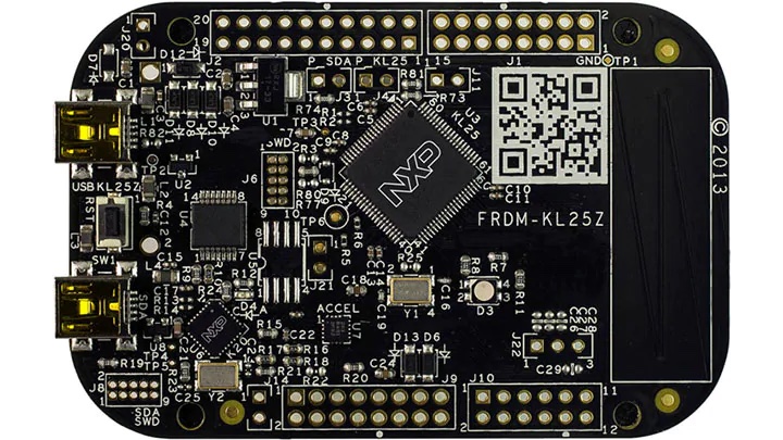
- This is the brains of the entire project. This microcontroller was chosen for a few reasons. First, I had some limited experience using this board for one of my classes. Second, this board is relatively low power, small, and had enough GPIO pins necessary for all of the components of the table. The original video I found used an Arduino for the project. I did not want to use an Arduino due to the extensive documentation and code already available. This would be too easy as the code and libraries I needed already existed. This board uses C and Assembly which is more challenging. I also needed to code everything myself rather than rely on existing libraries.
- WS2812B LED Strip
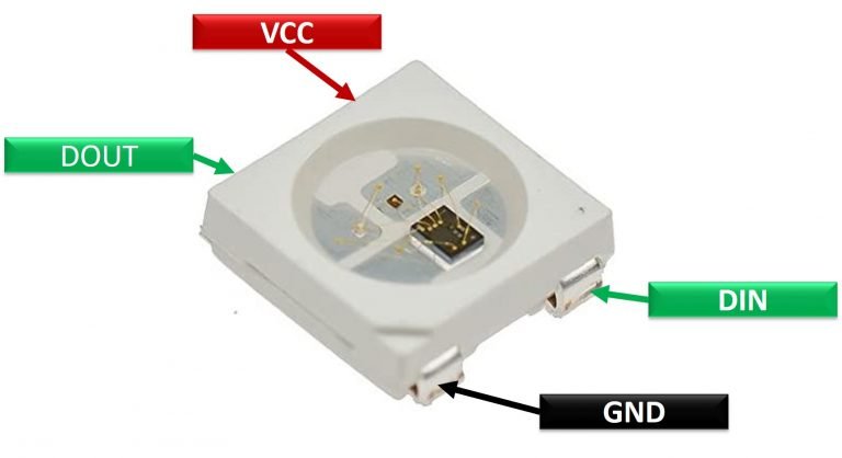 (Image from Microcontrollerlab)
- The WS2812B is probably the most popular standard among hobby DIY LED strips. These LEDs are individually addressable, low power, and look great. That being said, actually getting these LEDs to work is incredibly hard. I will go into this more later.
- OSOYOO IR Sensor
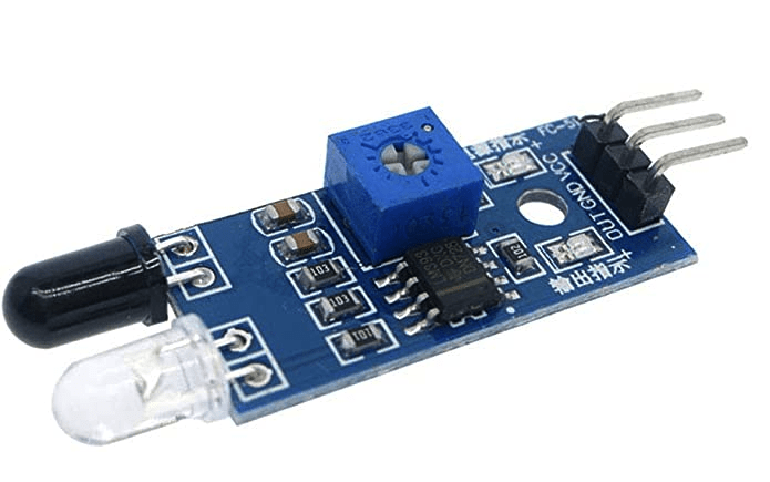
- Honestly, these sensors are not good. Each sensor is different from one another in terms of reliability. I had two sensors fail straight out of the box even when using the recommended 3.3V (5V is also said to work but if they failed at 3.3V, 5V would almost certainly be death). There is no data sheet available either. In general, these sensors were not pleasant to work with. Despite this, I still decided to use them because of their cheap price and because I already bought them.
- 74AHCT125 - Quad Level-Shifter
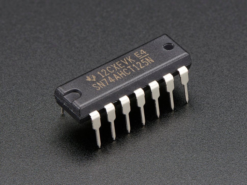 (Image from Adafruit)
- Ordinarily, one would not need a level shifter for this project. In my case, the FRDM KL25Z microcontroller only sends out 3.3V on its output pins. The LED strips used in this project require 5V data logic to be sent in order to drive them. The level shifter is used to shift the 3.3V to 5V as required by the LED strips.
- 300 Ohm Resistor
- A roughly 300 Ohm resistor is needed in the circuit in series with the Data Input of the LED in order to protect the LED strips.
- 1000 uF Capacitor
- A 1000 uF Capacitor is placed between the 5V and ground lines to the LED strip in order to protect the LED strip from sudden spikes in current draw. Since a capacitor gradually gets charged up, sudden changes in voltage will not have an impact on the LED strip.
Besides these main parts, I used a combination of single core wire and a breadboard.
The LEDs
As mentioned earlier in the parts list, the LEDs were the hardest component to implement into this table. The reason for this is that the WS2812B LEDs are addressable – meaning that if the LEDs are in a chain, the user can control the color of one specific LED in the chain rather than the entire chain. This gives me the flexibility needed to turn on a specific LED when a cup is placed down, but it complicates the project immensely.
Traditional LED strips are analog – meaning that you can change the color of the entire strip by changing the voltage sent to the strip. Blue might be 5V and Green might be 10V for example. You can only control the entire strip at a time.
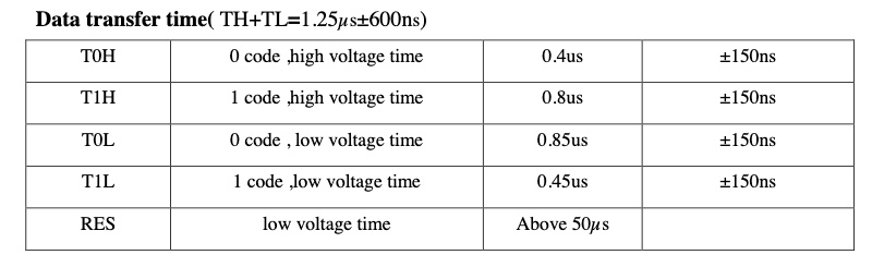
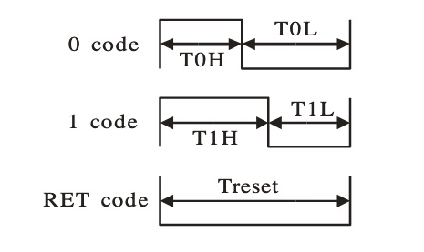
Digital LED strips, in comparison, take a fixed voltage. The WS2812B LEDs take 5V for example. The main difference here, however, is that Digital LED strips take in a data signal. The Digital LEDs have a small controller in each LED that processes the signal and spits the remaining signal out to the next LED in the chain. This allows for a user to set an individual LED to a specific color. For the WS2812B LEDs, each LED in the chain takes 24 bits – 8 for green, 8 for red, and 8 for blue. The period for one bit to be sent to the LEDs is 1.25 microseconds. In order to send a new color to an LED, there needs to be a period of low voltage for 50 microseconds. Two pictures from the data sheet are included below to better illustrate this.
Matching the Timing for the LEDs
As you can imagine, spitting out a signal with a period of 1.35 microseconds is challenging for a low powered board. The normal approach that I would use for a situation like this is bit-banging on the GPIO output. There are a few problems with this. One, the CPU on the board would have to do a lot of work to keep changing the signal so fast. For a 48 Mhz processor this is doable, but the CPU would almost constantly be clogged with work leaving any other functionality (sensing when a cup is placed down) slow. Another issue with this is that there would be more heat as the CPU is working harder. I am trying to make this table fanless so that it has silent operation. An increasingly hot processor would make this impossible.
My solution to this was to use DMA and a timer to spit out the signals on the GPIO pin. The board has a separate DMA module so the processor isn’t used heavily. The timer module is also separate. This would hopefully allow me to spit out the signal fast enough while not using a lot of CPU resources. I accomplished this by using 2 TPM timer channels and 3 DMA channels. If you look at the timing specification above, whether sending a 0 or 1 the first part of the signal is always high for at least 0.4 microseconds and is always low at the end for at least 0.4 microseconds. The time in between is where the actual signal is encoded. This way I could set up the timer as follows:
- After the channel 1 overflow happens, set the signal high.
- After the channel 2 overflow happens (0.4 microseconds later), set the signal to the value trying to be displayed.
- After the entire timer period overflows (another 0.4 microseconds later), set the signal low.
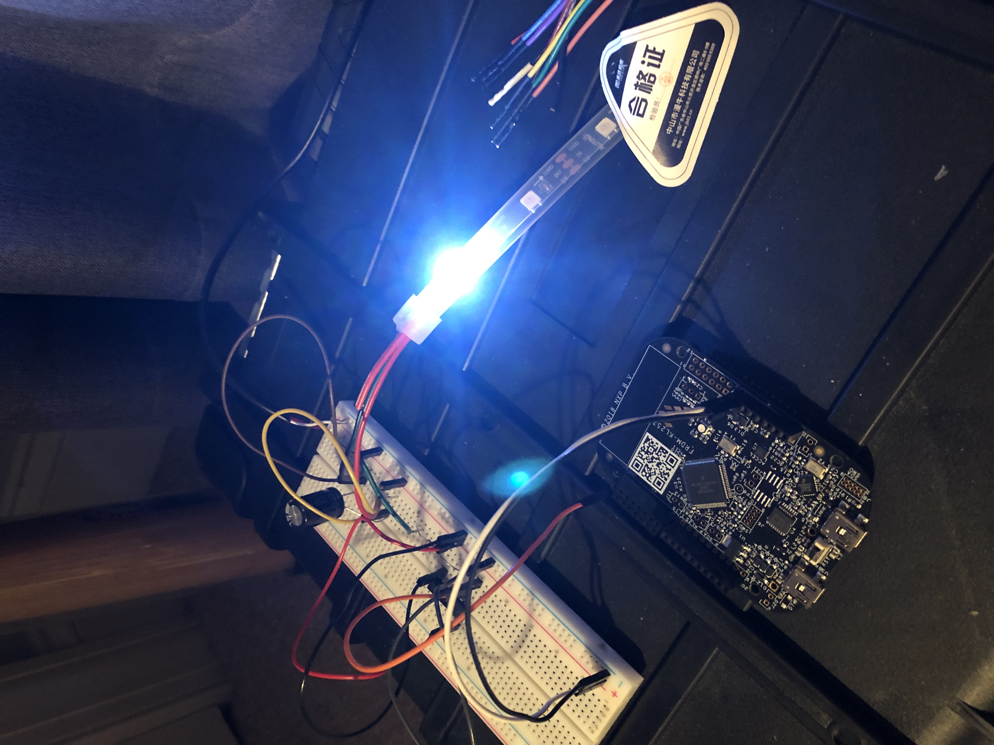
The bulk of the work on this project was spent trying to set this up. There are a lot of specifics with configuring DMA with the board that I was not aware of. There were also plenty of timer specifics that also made the project challenging. The main way I figured out all of this was by literally reading the board documentation from front to back. The importance of documentation for microcontrollers is huge. Below is a picture of my test setup when I got 1 LED to turn on. This was after about a month and a half of coding.
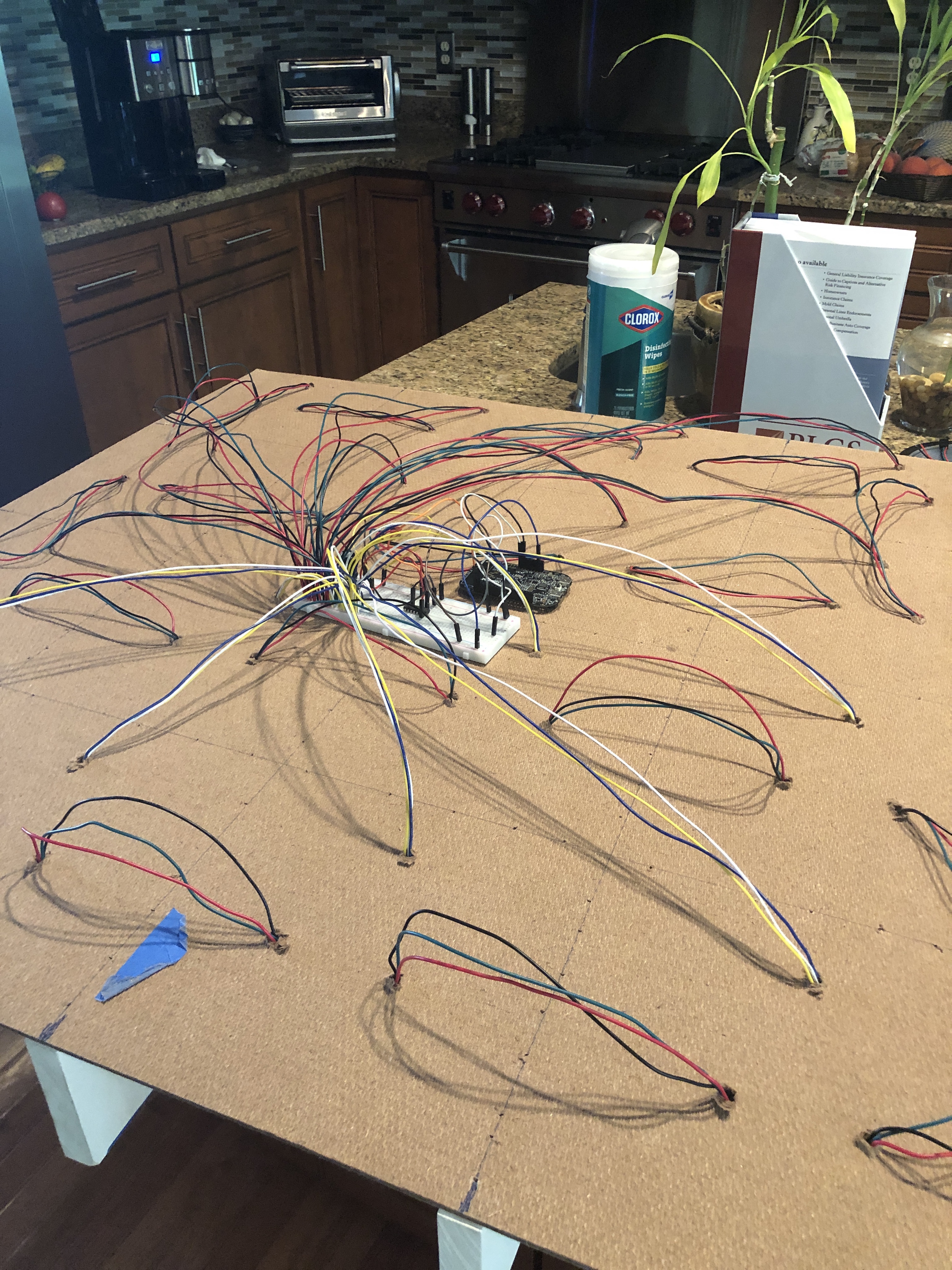
 This is a picture of the LEDs all wired into the table insert board.
The Proximity Sensors
As mentioned earlier, the proximity sensors used are terrible. They still, even with the finished product, make the table somewhat difficult to maintain. I just recently had a sensor fail after about a month of using the table. They are not reliable in the slightest sense of the word. Despite this, I will still go into detail about how I interfaced the sensors with the table.
The technology behind the sensors is actually rather simple. On the end of one sensor, there is an infrared transmitter and an infrared receiver. The sensor constantly sends an infrared light outwards and when it receives an infrared light back in its transmitter, it sends out a logic low (0V) to the output pin. If no signal is received, the signal on the output pin is high (3.3V in this case).
With this, I was able to set up each sensor as a GPIO input. When the signal went low, I triggered an interrupt and wrote an interrupt service routine to check which sensors were triggering. If a sensor was being triggered, the color of the corresponding LED with that sensor was changed. This is part of the reason why I needed to free CPU resources. If sending a signal to the LEDs was CPU intensive, I wouldn’t have been able to use interrupts to effectively check when a sensor was triggered. Below is a video of when I first got a proximity sensor working:
Putting It Together
Once I had the LEDs working and the sensors working on my test board, it was simply up to me to do the work to wire all of the LEDs together and connect the proximity sensors. There is one small caveat that I need to talk about.
All of the proximity sensors were wired up to the two ports on the board that support interrupts. I had exactly enough pins for each of the 16 sensors used in the table. Unfortunately, one of these pins, however, it configured as something differently by default when the board starts up. This means that if this specific sensor is triggered right when the table is plugged in, the board gets stuck in a different interrupt service routine. The solution to this is to just remove everything from the table when starting it up to make sure that this sensor is not triggered.
To conclude this post, I will include some pictures and videos of the wiring of the table as well as the table itself. There will also be a link to my Github repository with the code that I wrote for this project.
Github Repository
Photos and Videos
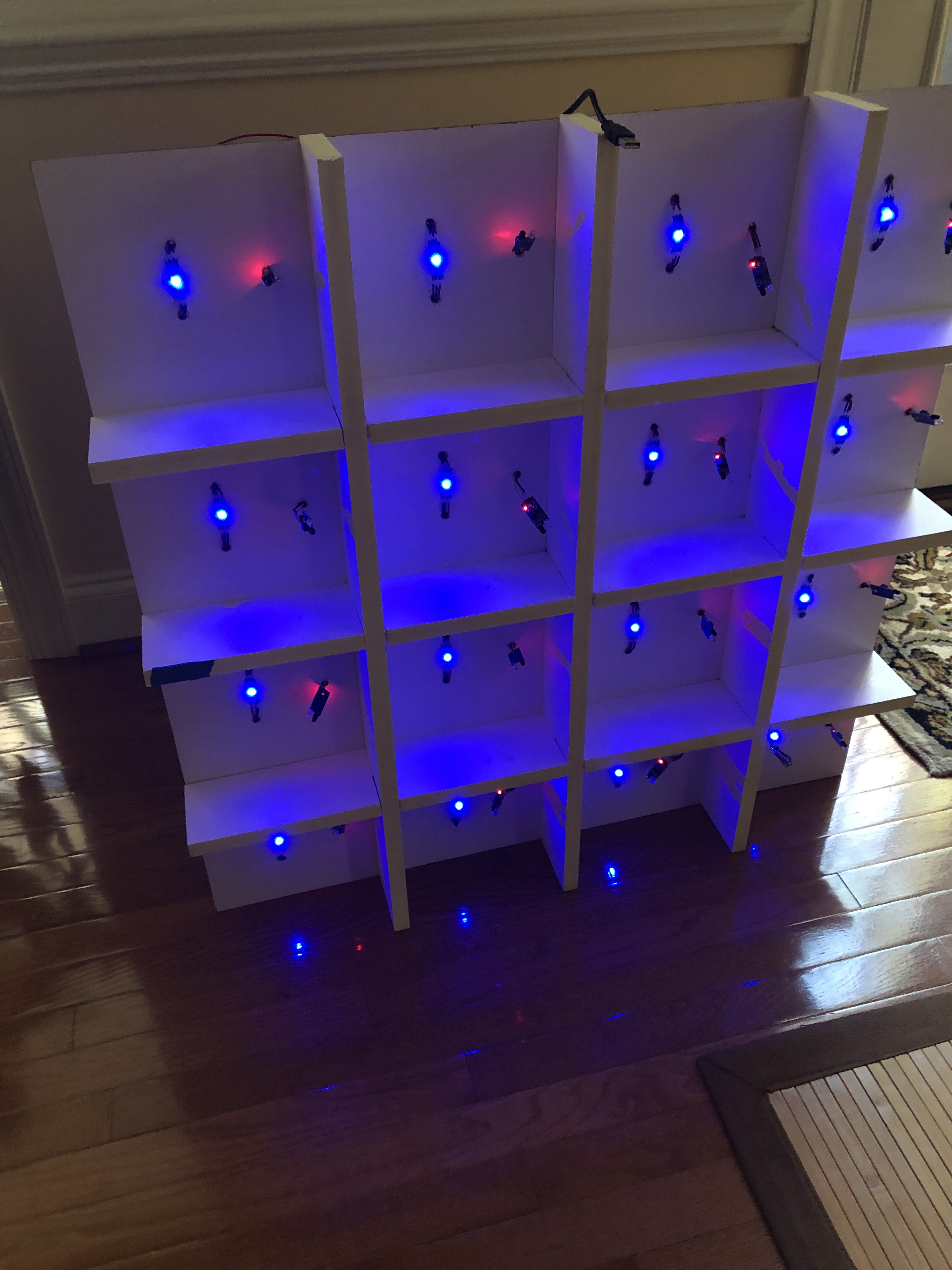
The back of the inside of the table with the LEDs and sensors wired together.
 The table insert from the front side.
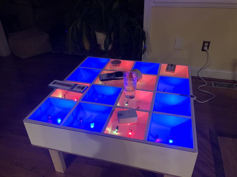
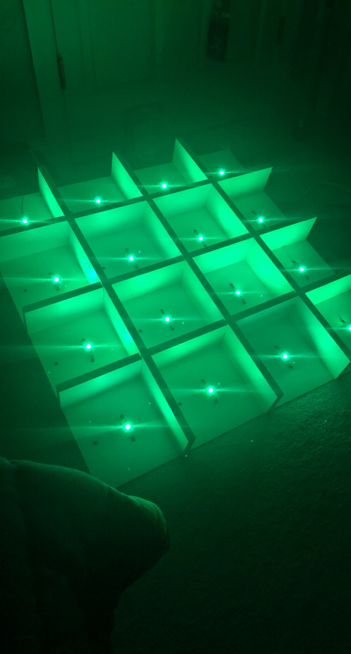
 Final Testing of the Table
First boot of the table.
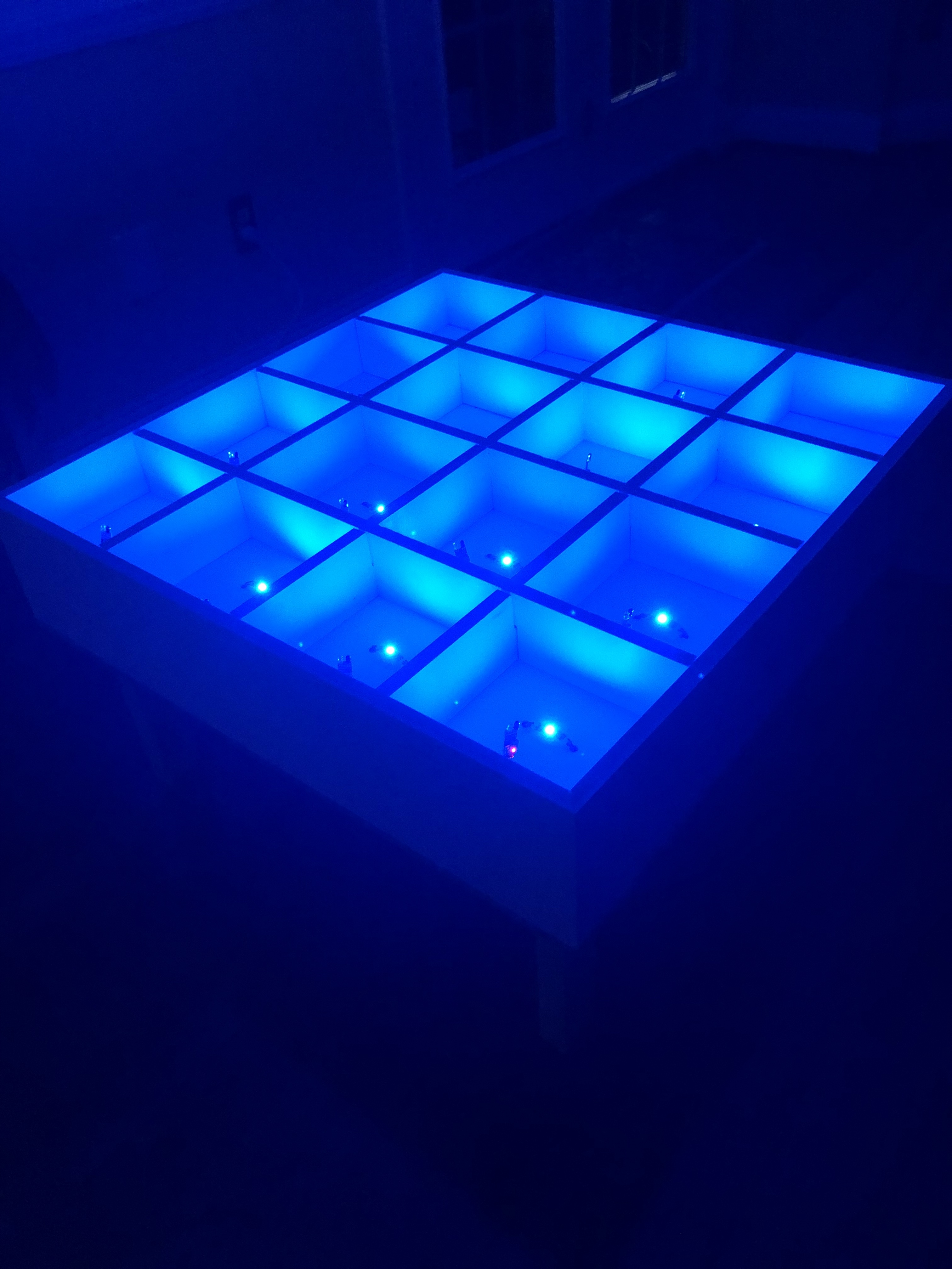
Table Demo
Final Demo of the Table
Disclaimer
I am not responsible for anything that goes wrong as a result of the posts on this site. By trying these methods, you are taking full responsibility for your actions.
View my Github here